
UTP02 Class I and Class II weighing instrument test procedure
This uniform test procedure (UTP) is to be followed by Trading Standards Officers or Accredited Persons when performing verification or inspection testing of Class I and Class II self-indicating digital non-automatic weighing instruments.
Scope
UTP02 describes the test procedure for the verification or inspection of Class I and Class II self-indicating digital non-automatic weighing instruments.
 Note
Note
A non-automatic weighing instrument (NAWI) can be Class I or Class II and must conform to the requirements of Regulations 40 to 60.
The working standards used must be Class F1 (for Class I) and Class F2 (for Class II).
Reference documents
Weights and Measures Act 1987 – NZ Legislation(external link)
Weights and Measures Regulations 1999 – NZ Legislation(external link)
OIML R76 – International Organization of Legal Metrology(external link)
Technical policies
TS-002 Information required on an Accredited Persons test sheet
TS-006 When is a full verification test required for weighing and measuring instruments
TS-007 Eccentricity test on weighing instruments
TS-008 Repeatability test on weighing instruments
TS-009 Discrimination test on digital weighing instruments
TS-011 General sealing requirements for weighing and measuring instruments
TS-012 Using indicators in expanded or test mode on weighing instruments
TS-014 Secondary indicators on weighing instruments
TS-024 When an auxiliary (peripheral) device is fitted to a weighing instrument
Appendix 1: Example of how to determine error on a Class II weighing instrument (where e ≠ d)
Health and safety requirements
General
- Requirements of the site where work is to be completed
Trading Standards
- Trading Standards – Hazard and risk register
- Safe Working Practices:
- SWP11 Weighing instruments < 300 kg
- SafetyCulture risk assessment
Accredited Persons
- Health and Safety at Work Act - shared duties and expectations
- Accredited Person Quality Management System and associated documentation; test procedures and test sheets
Conformance with Certificate of Approval
- Confirm that the instrument is marked with its Certificate of Approval number, and
- Confirm that the instrument complies with any conditions specified in the Certificate of Approval, as per Regulation 9(3) of the Regulations:
- This may include requirements in relation to make, model, sealing requirements, labelling, marking requirements, compatibility specifications etc.
Refer to the approval certificate register for details of all certificates issued by Trading Standards.
Visual inspection
The instrument must be:
- issued with a Certificate of Approval
- marked with its Certificate of Approval number
- compliant with the requirements, conditions and technical specifications detailed in the Certificate of Approval
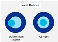
- set to its reference (horizontal level) position. Before performing any tests, make sure that if the weighing instrument is equipped with a level bubble, then it is set to level. If not, then adjust the feet to make it level
- segment checked, as a digital number is made up of 7 segments, and this test confirms that all segments are working. To perform the test, the instrument is turned off and then back on. Then, as it goes through its start-up cycle, it will perform a segment check, which can be observed.
Note
A segment check is not applicable for displays on which a failure is evident, for example, non-segmented displays, screen-displays, matrix-displays, etc.
Performance tests
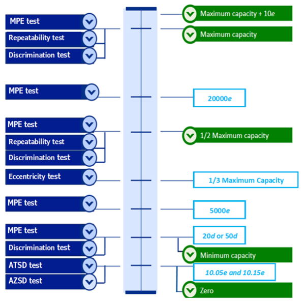
The diagram below shows where tests are to be performed in the scale range, from zero at the bottom to maximum at the top, for a Class II weighing instrument:
Accuracy of zero setting device (AZSD)
This test only applies to instruments with verification scale interval ‘e’ ≥ 100 mg.
Procedure
Weighing instruments – where ‘e’ ≠ ‘d’
- Exercise the instrument (if this is the first test being performed).
- Zero the instrument by pushing the zero-setting button.
- When the indication has stabilised and the zero annunciator is illuminated, add a load equal to 10.05e.
- The indication should either read 10e or 10.1e.
- If it indicates any other reading then the instrument fails.
- Add an additional load of 0.1e to the load receptor, making the total load 10.15e.
- If the initial indication was 10e, then the instrument must read 10.1e; but if the initial indication was 10.1e, then the instrument must read 10.2e, the instrument passes this test.
- If it indicates any other reading then the instrument fails.
Weighing instruments – where ‘e’ = ‘d’
- Exercise the instrument (if this is the first test being performed).
- Zero the instrument by pushing the zero-setting button.
- When the indication has stabilised and the zero annunciator is illuminated, add a load equal to 10.25e.
- The indication should read 10e.
- If it indicates 11e then the instrument fails.
- Add an additional load of 0.5e to the load receptor, making the total load 10.75e.
- If the indication reads 11e, the instrument passes this test.
- If it indicates 10e it fails.
Accuracy of tare setting device (ATSD)
This test only applies to instruments with verification scale interval ‘e’ ≥ 100 mg.
Procedure
Weighing instruments – where ‘e’ ≠ ‘d’
- Exercise the instrument (if this is the first test performed).
- Perform this test at a point above minimum capacity (20d or 50d) but not above the range of the tare-setting device.
- Place the load on the weighing instrument.
- Push the tare button.
- This will set the indication at 00.00 and reduce the weighing range
- When the indication has stabilised and the tare annunciator is illuminated, add a load equal to 10.05e.
- The indication should either read 10e or 10.1e.
- If it indicates any other reading then the instrument fails.
- Add an additional load of 0.1e to the load receptor, making the total load 10.15e.
- If the initial indication was 10e, then the instrument must read 10.1e; but if the initial indication was 10.1e, then the instrument must read 10.2e, the instrument passes this test.
- If it indicates any other reading then the instrument fails.
Weighing instruments – where ‘e’ = ‘d’
- Exercise the instrument (if this is the first test performed).
- Perform this test at a point above minimum capacity (20e or 50e) but not above the range of the tare-setting device.
- Place the load on the weighing instrument.
- Push the tare button.
- This will set the indication at 00.00 and reduce the weighing range
- When the indication has stabilised and the tare annunciator is illuminated, add a load equal to 10.25e.
- If the indication displays 10e, go to step 6
- If the indication changes to 11e, the instrument fails this test.
- Add an additional load of 0.5e to the load receptor, making the total load 10.75e.
- If the indication displays 11e, the instrument passes this test.
- If the indication stays the same, the instrument fails this test.
Eccentricity test
Procedure
- Zero the instrument.
- Divide the load receptor into four approximately equal quadrants.
- Determine the load to apply in accordance with Technical Policy TS-007.
- Place the load into the first quadrant.
- Record the indication.
- Determine the error and check if it is within the mpe for the load applied.
- Remove the load.
- Repeat step 4 to 7 for each of the other quadrants.
- If any of the errors are outside of the mpe, the instrument fails the eccentricity test.
- If the errors are within the mpe, the instrument passes the eccentricity test.
Discrimination test
Procedure
- Zero the instrument.
- Apply the minimum capacity.
- Apply a discrimination test load:
| Discrimination test load | Instrument |
|---|---|
| 1.4 x d | Instruments fitted with auxiliary indicating devices where ‘e’ is not equal to ‘d’ and d ≥ 5 mg. |
| 1.4 x e | Instruments fitted with auxiliary indicating devices where ‘e’ is not equal to ‘d’ and d< 5 mg. |
| 1.4 x e | Instruments, where ‘e’ = ‘d’ |
- Repeat this test (step 3 to 5) for half-maximum capacity and maximum capacity.
- If the instrument has switched between the two indications and not settle on one or didn’t change, then it will fail the test.
- Repeat this test (step 3 to 5) for half-maximum capacity and maximum capacity.
For more information, see Regulation 57(3) of the Weights and Measures Regulations 1999(external link).
Note
It is acceptable to use a load of ≤1.4 x the scale interval to perform this test.
Repeatability tests
Procedure
- Zero the instrument
- Test at half-maximum capacity
- Test load = plus or minus 10 percent of half-maximum capacity.
- Apply the load. Allow the instrument to stabilise and record the reading.
- Remove the load and allow the instrument to return to zero.
- Repeat steps 2 to 4, five more times (for a total of six tests).
- Test at maximum capacity.
- Test load = less than 10% in deficiency of maximum capacity.
- Note: If the instrument has a tare adding device, then the maximum capacity is the instrument’s maximum capacity plus the value of any additive tare.
- Perform the maximum capacity test a total of six times using the same procedure in steps 2 to 5.
- Check if the greatest difference between any two readings at half-maximum capacity or maximum capacity fall within the absolute value of the mpe.
Note
Error is applied in terms of the verification scale interval ‘e’.
- If they do, the instrument passes this test.
- If any result does not, the instrument fails this test.
For more information, see:
- Regulation 58 of the Weights and Measures Regulations 1999(external link)
- TS–008 Repeatability test on weighing instruments
Weighing performance tests
Test Loads: Use the following test loads.
- Where the MPE changes
- Maximum capacity (if overload blanking occurs at this point, a test load of maximum capacity less 5 e should be used)
- Where the value of e changes (multi-interval instruments – instruments that have 1 weighing range which is divided into partial ranges each with different scale intervals. The weighing range is determined automatically according to the load applied). Note: Always use a load 5 e less than this value
- Maximum capacity plus maximum capacity of tare additive device (if applicable).
Notes
- Use at least 5 different test loads (including those above). Where the maximum capacity is less than:
- 20,000 e (for a Class II instrument), or
- 200,000 e (for a Class I instrument)
A test load which is between half-maximum capacity and maximum capacity can be used for the test (to make a total of 5 test loads).
- When testing multi-range instruments (instruments having 2 or more weighing ranges with different maximum capacities and different scale intervals for the same load receptor, each range extending from 0 to its maximum capacity), each range is tested separately.
Procedure
- Zero the instrument.
- Apply each test load from minimum to maximum.
- Determine the errors.
- Check if any error is within the mpe for the load applied. This depends if the test is a verification or inspection.
- While at the maximum capacity of the instrument, apply an additional load of 10e to the instrument. This should cause the instrument indication to blank as it has exceeded its stated maximum capacity.
- Remove the weights in decreasing order.
- Use at least three different loads (maximum, half-maximum, and minimum capacity).
- Check if any errors are within the mpe for the load applied.
- If errors are not within the mpe, then the instrument fails the weighing performance test.
- If errors are all within the mpe or the indication equals the load, then instrument passes the weight performance test.
Tare weighing test
Purpose of the test
These tests are only performed when conducting a verification test.
This test is performed to confirm that when a tare is entered into an instrument it will:
- not exceed its stated capacity,
- weigh accurately to within the mpe allowed for the test load.
Procedure: Subtractive Tare
- Place a load equal to the maximum tare value on the instrument.
- Increase the load by 10e.
- When stable, press the tare key.
- The instrument should not accept this value.
- Remove the 10e load.
- Press the tare key again.
- Confirm that:
- The indication reverts to zero.
- An indication that a tare is entered is displayed.
- Remove the test load.
- Confirm that the indication either blanks or displays a tare reading.
- Apply a load equal the the maximum capacity of the tare.
- Check that the indication is within the mpe for the load applied.
- The instrument passes if:
- It blanks when it exceeds the range of the tare value +10e.
- It is within the current mpe allowed for the load.
Procedure: Additive tare
- Place a test load equal to the maximum tare value on the instrument.
- Increase the load by 10e and press the tare key.
- Confirm that the instrument doesn’t accept this value.
- Remove the 10e load, let the indication stabilise, and press the tare key.
- The instrument should now accept the load.
- Confirm that:
- The indication reverts to zero.
- An indication that a tare is entered is displayed.
- Remove the test load.
- Confirm that the instrument either blanks or shows a tare reading.
- Apply a load equal to the sum of the maximum capacity of the instrument and the maximum tare value.
- Check that the indication is within the mpe allowed for the load.
- The instrument passess if:
- It blanks when it exceeds the range of the tare value +10e.
- It is within the correct mpe allowed for the load.
Auxiliary devices
- An auxiliary device may only receive data or send a request to release it.
- It must not have the ability to alter any metrological relevant configuration or parameter of the instrument it is connected to.
- Any data received and displayed by an auxiliary device must replicate exactly the data displayed on the main instrument.
Check the certificate of approval to confirm if certain auxiliary devices are permitted to be connected to an instrument.
Appendix
Determining error on an instrument where e ≠ d
In the example below a Class II digital weighing instrument is being tested for error at Maximum Capacity. The instrument is stamped with a mark of verification, on inspection MPE applies.
- Maximum Capacity: 1200 g
- Minimum Capacity (50d): 0.5 g
- Verification scale interval (e): 0.1 g
- Actual scale interval (d): 0.01 g
In this instance (e = 10d).
A test load of 1200 grams is placed on the load receptor. The instrument indicates 1200.13 g.
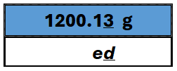
The error can be determined by subtracting the value of the test load from the indicated value:
- Error = Indication - Load
- Error = 1200.13 g - 1200.00 g
- Error = +0.13 g
In this instance e = 0.1 g. The error is determined to be 0.13 g (1.3 e).
Using Table 9 of the Regulations, the MPE for this instrument at Maximum Capacity is determined to be +/-2 e (0.2 g).
The error is less than the MPE, the instrument passes this test.