
TS–027 Design and construction requirements for working standard measures of volume
This policy prescribes the requirements for the design and construction of working standard measures of volume used by an Accredited Person when inspecting and verifying trade approved liquid measuring instruments.
 NOTE
NOTE
This policy does not apply to conical brim measures (see below picture).
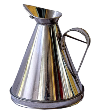
A metallic conical measuring container with a wide brim and a side handle.
Reference documents
- OIML R120 – Standard capacity measures for testing measuring systems for liquids other than water [PDF, 1.64 MB](external link)– International Organization of Legal Metrology (OIML)
- NIST105-3 – Specifications and Tolerances for Graduated Neck Type Volumetric Field Standards [PDF, 998 KB](external link) – National Institute of Standards and Technology (NIST)
Policy
Trading Standards (TS) require the following design and construction specifications to be met for all Working Standard measures of volume used by an Accredited Person (AP) for inspection and verification of approved measuring instruments.
Deviations from the design and construction specifications detailed in this policy may require additional examination by Trading Standards to ensure that the modified design meets the accuracy and performance requirements for the volume measure to be used as a Working Standard.
Retrospective
These specifications are not intended to make obsolete those measures, which have been tested by Trading Standards and are currently in use by an AP as a Working Standard. However, all new Working Standard measures of volume submitted to Trading Standards after 1 June 2020 must meet the design and specification requirements detailed in this policy.
The Working Standard measures of volume that are currently in use by an AP may continue to be used as long as they:
- maintain the current tolerances
- meet calibration repeatability requirement of nominal volume, and
- their performance is adequate to meet the requirements of the weights and measures legislation.
The requirements in this document are not retrospective. However, Trading Standards recommend that a current Working Standard measure of volume be retrofitted to meet new requirements when major repairs or other modifications are made. All design changes should be evaluated by Trading Standards prior to the modifications being made.
Disclaimer – Health & Safety Considerations
This policy document does not purport to address the health and safety issues associated with the use or handling of hazardous materials, operations and equipment. It is the responsibility of the owner and user of the Working Standard to establish appropriate safe working practices and to determine the applicability of any regulatory limitations prior to use.
Design and type of construction material
| Description of standard capacity measure | Nominal capacity (L) |
|---|---|
| Standard test measures | ≤ 20 |
| Proving tanks | > 20 |
Standard Test Measures (5 L, 10 L and 20 L)
- Standard capacity measures used for the testing of measuring systems must be of suitable nominal capacities (1) and must be sufficiently strong and robust and made of stainless steel, or mild steel with a suitable interior coating. Proposals for the use of other materials must be submitted to Trading Standards for approval.
- The complete body of test measure is made of identical material. Other non-integral hardware such as visi-gauge may be made of other materials provided the hardware is durable and suitable for its intended purpose.
- Any cross section taken in a plane perpendicular to the vertical axis must be circular. The volume of a standard must be established without the use of fillers, adjusting plugs, or cavities of any kind.
- Recommended top and bottom cone pitches are provided in Table 1 below. Cone pitches are intended to facilitate complete emptying and draining. Deviation from the recommended cone pitch requires a laboratory evaluation for repeatability and assurance of no air entrapment.
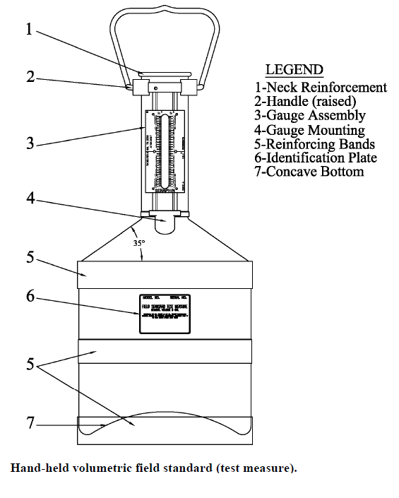
- It must be ensured that the liquids are easily delivered to and from standard test measures, and that no pockets, dents or crevices capable of trapping the liquid or air or vapour are present. The bottom of hand-held test measures must be concave to prevent the distortion of the measure during filling due to the weight of the liquid.
- Where standard measures are mounted on a truck or trailer, means must be provided to secure and maintain them in a level position, during testing and use.
- For measures that are “to deliver” or “to contain”, the outlet or valve should be restricted to control the drainage rate down the interior wall of the measure to a speed not greater than 1 cm / s, or to preserve the integrity of the meniscus , whichever is the slower.
Proving Tanks (> 20 L)
- Proving tank measures used for the testing of measuring systems must be of suitable nominal capacities (1) and must be sufficiently strong and robust and made of stainless steel or mild steel with a suitable interior coating.
- The complete body of proving tank is made of identical material. Other non-integral hardware such as visi-gauge may be made of other materials provided the hardware is durable and suitable for its intended purpose.
- Proving tanks with top or bottom cone must meet the recommended cone pitches provided in TABLE 1 below. Cone pitches are intended to facilitate complete emptying and draining. Deviation from the recommended cone pitch requires a laboratory evaluation for repeatability and assurance of no air entrapment.
- Proving tanks must be provided with drain valves at the bottom part; they should be designed with a top neck and may be designed with a bottom neck.
- For testing certain types of measuring systems (for example, those for the reception of milk), it may be easier to use proving tanks of the brim measure type.
- It must be ensured that the liquids are easily delivered to and from the proving tanks and that no pockets, dents or crevices capable of trapping the liquid, air or vapour are present.
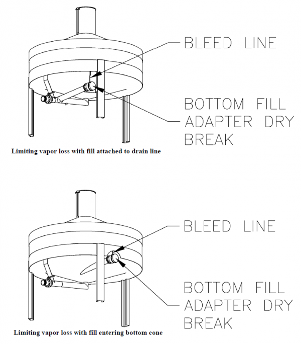
- Bleed lines (2) must be provided where air may be entrapped in the dry break coupler and lines going to it.
(2) A bleed line is a small bore line that automatically prevents air entrapment in a pipe, valve, dry break coupling, or other fitting that is part of the calibrated volume of the field standard during calibration and top loading applications. - The nominal volume or zero lines must extend across the entire width of the scale plate and must be clearly identified with the nominal volume of the volumetric field standard.
Requirements for the neck and visi-tube
- The diameter of the neck must be large enough to prevent the trapping of liquid, air or vapour, and to facilitate cleaning of the measure. The neck axis must be perpendicular to a level horizontal plane.
- The diameter of the neck must be suitably sensitive to detect changes in the liquid level in the measure to the required measurement accuracy. As a minimum requirement a difference of at least 3 mm in the liquid level in the neck must be equivalent to the absolute value of the maximum permissible error of the standard capacity measure.
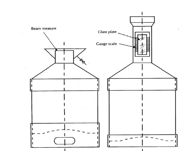
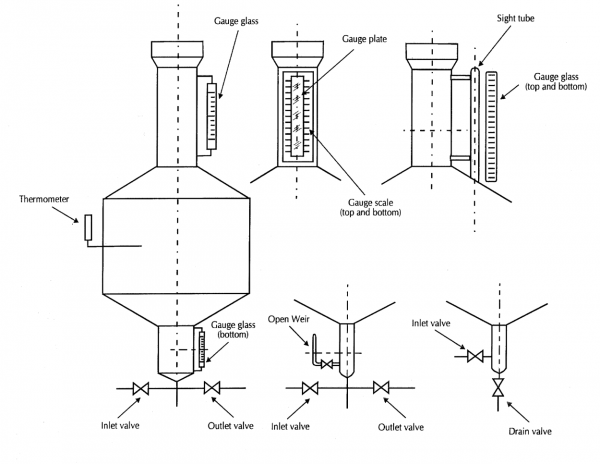
- The top neck should be provided with gauge plate(s) and/or have an integrated visi-tube (measurement tube) made of glass or transparent plastic material. The gauge plate or the measurement tube must be marked with graduated scale marks.
Alternatively, the proving tank must be fitted with a separate fixed or sliding rustproof graduated metal plate inside the neck and on the collar to enable to read measurement errors. Where a sliding plate is provided, it must have provisions to be sealed.
Where a graduated plate is used in combination with a visi-tube, the plate must be installed in close proximity to the tube for easy reading of measurement errors without parallax errors.
NOTE: The graduated scale marks must correspond to the nominal capacity and to at least 1 % of the nominal capacity, in plus and in minus. The scale marks on the metal plate fixed to the neck part, must be inscribed on both edges of the plate, adjacent to the window/tube.
Where a proving tank has a bottom neck (see Example designs of volume measures section below), the neck must be provided with glass plates or a separately fixed gauge glass(es) similar to the top neck, with scale marks corresponding to volumes of only 0.5 % in plus or in minus of the nominal capacity. - Where an outer weir (or collar) is provided, it must be lower than the actual neck to allow the measure to be struck off.
- The diameter of the visi-gauge tube connected to the top and bottom necks must be large enough to ensure that capillary or meniscus effects do not introduce additional uncertainties such that the maximum permissible errors are exceeded.
- The recommended graduation scale marks and nominal inside diameter of the measurement tube is detailed in Table 1 below.
Adequate support
- The body of the measure and associated support structure must be designed to prevent distortion and provide protection against damage when in transit on a trailer or truck and when fully loaded. The bottom of the measures must be of adequate thickness to prevent distortion when filled.
- Any supporting structure of the measure consisting of legs, framework, or mounting structure must not be attached directly to the body of the prover. Legs or other mounting structure must be attached either to an exposed portion of a reinforcing band that extends beyond the body of the prover or to the outside of a reinforcement plate that is attached to the body.
- Ladders and work platforms (with appropriate safety hand rails), when required, must be secure and designed to support the operator while reading or servicing the neck-gauge assembly. The ladder must be so constructed that there is no distortion of the prover when the ladder is in use. Ladder rungs should be constructed of a non-slip design/material.
Drain facility
- A gravity discharge line, between the measure and the shut-off valve, must have a downward slope to prevent water retention. Valves should be evaluated carefully and only those that have minimal liquid retention should be used.
- In case of a proving tank, all gravity and pump discharge lines downstream from the shut-off valve must be positioned so as to ensure complete emptying of the measure.
- For measures that are “to deliver” or “to contain”, the outlet or valve should be restricted to control the drainage rate down the interior wall of the measure to a speed not greater than 1 cm / sec, or to preserve the integrity of the meniscus, whichever is the slower.
Secure and level position
- The neck axis must be perpendicular to a level horizontal plane, and the measure must be level within applicable tolerances whether levelled at the neck, suspended by the bail handle, or placed on a level surface as determined by a precision spirit or electronic digital level. Where applicable, a level indicator must be provided and an adjustment mechanism to set the measure vertical.
- In case of a proving tank, a precision spirit or electronic digital level must be provided at least two locations, 90 degrees apart around the measure and have provisions to adjust the orientation of the standard until the neck is as close to vertical as possible.
- Where a measure is mounted on a truck or trailer, means must be provided to secure and maintain them in a level position, during testing and use.
Sealing
- Where a measure has an adjustment plunger, they must not move after adjustment of the volume and must be capable of being sealed.
- Where a measure incorporates a valve, for the purposes of draining the contents of the measure, the valve must be able to be sealed to the measure by means of a wire and lead seal (or any approved seal by Trading Standards) to ensure it is not replaced, or its threaded position altered, during normal use.
Thermometer wells
Where it is required to record the temperate of the test liquid, the proving tank must be provided with thermometer wells. The minimum recommended number of thermometer wells is given below:
| Nominal capacity of a proving tank | Minimum number of thermometer wells |
|---|---|
| ≤ 500 L | 1 |
| > 500 L ≤ 2000 L | 2 |
| > 2000 L | 3 |
Marking requirements
Information marked on a measure must be engraved, embossed or affixed by some other permanent means directly on the measure or on a metal plate that is permanently attached to the measure in an area that is relatively protected from damage or normal wear. The minimal information required to be marked is:
- nominal capacity
- serial / identification number / code, and
- year of manufacture.
Additionally, the registered business name, trading name, trademark or identifier of the accredited organisation may be marked on the measure.
Table 1 – Dimensional requirements
| Nominal Capacity (3) (L) | Maximum Upper Neck Inside Diameter (4) (mm) | Visi-Gauge Tube Inside Diameter (4) (mm) | Maximum Graduation Scale Marks on Visi-Gauge Tube or Gauge Plate (mL) | Minimum Top Cone Pitch | Minimum Bottom Cone Pitch |
|---|---|---|---|---|---|
| 5 | 30 | 13 | 2.5 | 35° | - |
| 10 | 43 | 13 | 5 | 35° | 20° |
| 20 | 60 | 13 | 10 | 35° | 20° |
| 50 | 95 | 13 | 25 | 35° | 20° |
| 100 | 127 | 16 | 100 | 25° | 20° |
| 200 | 178 | 16 | 100 | 25° | 20° |
| 500 | 254 | 16 | 250 | 25° | 20° |
| 1000 | 432 | 16 | 500 | 25° | 20° |
| 2000 | 432 | 16 | 1000 | 25° | 20° |
| 3000 | 508 | 16 | 1500 | 25° | 20° |
| 5000 | 508 | 16 | 2500 | 25° | 20° |
(3) For a measure that has a nominal capacity between two capacities listed above, the sizes prescribed for the lower capacity measure must be applied.
(4) Neck diameter may vary; the critical factors to be considered, which affect neck diameter, are the:
- volume above and below nominal
- graduation sizes
- minimum space between graduations, and
- use of fill pipes and vapour recovery systems.
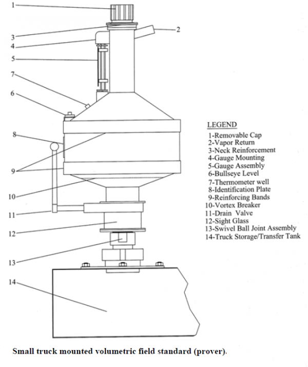
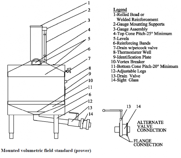
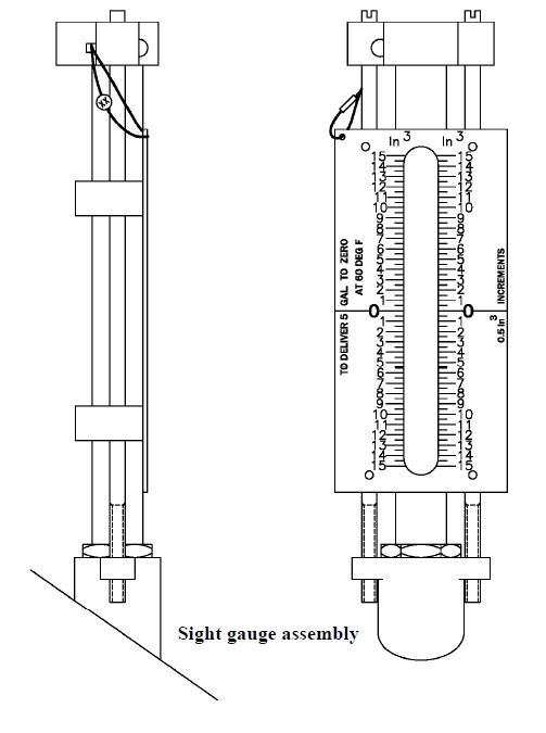
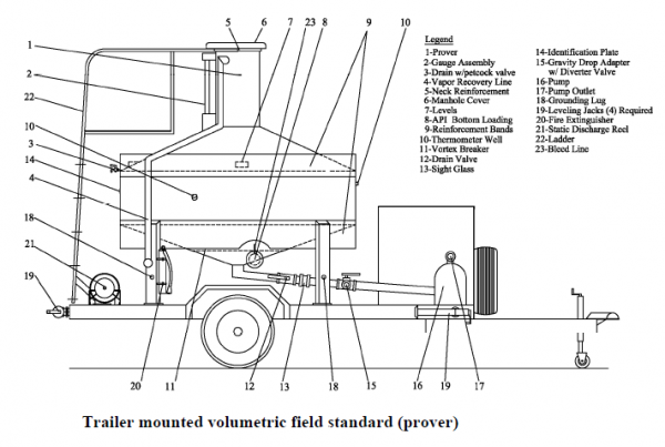
Example designs of volume measures
Trade Measurement — Technical Policy
| Policy number: | TS - 027 |
|---|---|
| Effective date: | March 2020 |
| Version date: | August 2025 |
| Version number: | 2 |
| Policy name: | Design and construction requirements for working standard measures of volume |
| Reviewed by: | Davis White, Principal Adviser Legal Metrology |
| Approved by: | Phil Sorrell, Manager Accreditation and Enforcement |